

An energy storage type emergency shut-off valve is a safety device that provides reliable local, remote, or automatic emergency shut-off functions when pipeline pressure is abnormal, a pipe bursts, or a fire occurs. The self-actuated emergency shut-off valve does not require an external power source and features a compact structure, simple installation and operation, fast response, stable performance, and economical cost.
It is widely used in medium and low production wellheads (such as tight gas, shale gas, etc.), gas storage facilities, and high-pressure pipeline shut-off applications.
I. Energy Storage Emergency Shut-off Device
 It is a crucial safety barrier in oil and gas extraction. To ensure the effectiveness of this safety measure, historically, various methods of emergency shut-off have been attempted, including electric-hydraulic, pneumatic-hydraulic, and self-actuated spring types. However, these methods all have certain limitations, especially the issue of power storage has never been satisfactorily resolved. This is because it is difficult to achieve continuous power online, and once power is lost, the valve cannot be closed. It was not until 2014 that a new type of energy storage emergency shut-off device with permanent power supply was developed by Daume, marking another significant contribution to social safety by the people.
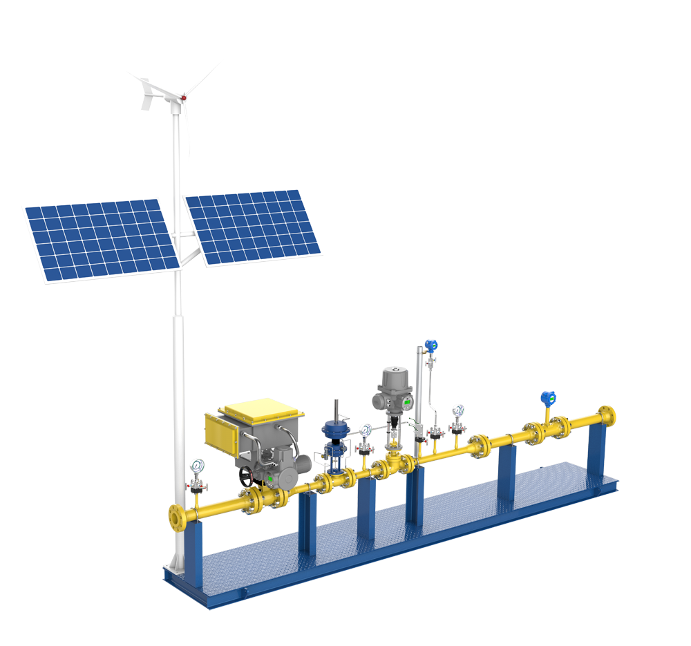
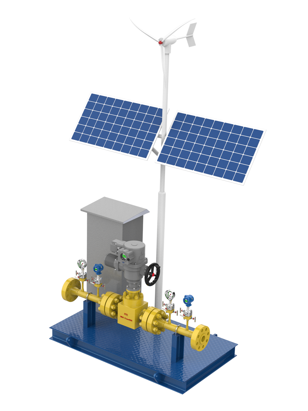
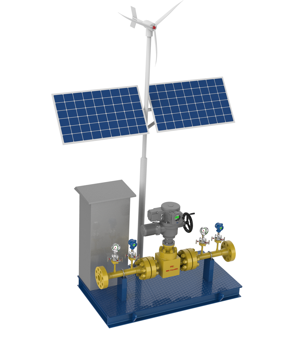
II. Components
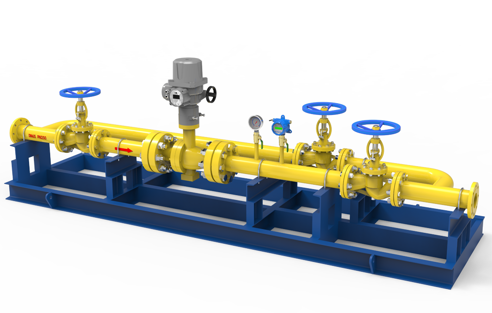
- high-pressure gate valve/ball valve,
- motor,
- mechanical transmission,
- control system,
- energy storage unit.
It represents the current generation of products that are the simplest in structure, most comprehensive in function, most stable in performance, and require no maintenance.
III. Working Principle
After the device is connected to a 220V priority power supply, it splits into two power paths: one supplies the motor, and the other continuously charges the energy storage device to ensure continuous power supply;
The device is also equipped with a pressure transmitter installed on the pipeline, and its output signal is connected to the control unit. The control unit can monitor the changes in pressure signals in real-time, and once it detects that the pressure in the pipeline exceeds the preset range, it will issue a command to drive the motor to operate and close the valve through the mechanical transmission mechanism.
IV. Why use energy storage multi-function device?
The following form is a compare table introduce the differences between the regular type and energy storage multi-function device.
|
Device Type |
Self-operated Wellhead Emergency Shut-off Device |
Energy Storage Multi-Function Wellhead Control Device |
|
Control Method |
Oil Pressure + Spring |
Utility Power + Energy Storage Device |
|
How It Works |
Relies on manual pump to pressurize the hydraulic oil in the tank through the pipeline system, hydraulic valve set, and various functional solenoid valves into the accumulator. When the oil pressure in the accumulator exerts a force greater than the spring force, the spring is compressed to a certain extent and remains in a compressed state for a long time. Then, through manual periodic re-pressurization, the spring’s compressed range is maintained to be greater than the valve stroke, and the pressure-holding solenoid valve is closed. When the high or low pressure values in the pipeline reach a certain level, the high or low pressure pilot valve opens, and the pressure-holding valve opens, causing the oil pressure in the accumulator to drop rapidly. The spring’s reactive force is released, pushing the valve stem towards the closing direction until the valve is closed. |
1) Priority 220V access device is divided into two paths, one for motor power supply, and the other two for real-time charging of the energy storage device, ensuring permanent power online; |
|
Requires Power Supply |
24VDC |
Not Required |
|
Gas Suction Pressure Device |
Required, and can cause ice blockage |
Required and can easily cause ice blockage |
|
Process Control |
1) Large and intertwined pipeline system; |
With Built-in Control Unit |
|
Guarantees to Achieve Emergency Shut-off Function |
1) Ensure uninterrupted 24V power supply; |
1) Ensure that the cable connection between the pressure transducer and the device is intact; 2) Ensure that its own control system is intact. |
|
Daily Maintenance Volume |
Requires regular maintenance |
Maintenance-Free |
|
Failure Rate |
High |
Extremely Low |
|
Subsequent Expansion Space |
None |
With its own control system, it can provide a complete solution for intelligent control of the entire wellhead |


